Plastic injection molding is by far the most common way to mass-produce custom parts for every imaginable application and industry. It is fast, efficient and cost-effective, but there are design rules that need to be followed to avoid common defects and possible manufacturing delays.
It’s important for product developers to be familiar with these common defects so that your design is optimized to prevent them when possible or to make tolerable allowances on the finished product. So today we are going to take a look at the five most common defects in injection molding and their solutions.
Weld Lines
Problem: Weld lines are formed when plastic resin is forced around an obstruction in a mold tool and reforms on the side opposite the gate. This customary mark is caused by differential rates of cooling in the resin where it rejoins.
Solution: Weld lines may be unavoidable in many cases. But we will work with you to optimize many parameters that cause this defect. We could create more cooling circuits at the area where weld lines form, camouflage the weld line within the design, move gate locations, add multiple gates or even use lighter colors to help hide the weld lines.
Gate Witness Mark
Problem: The gate is the nozzle from which liquid plastic is injected into a mold tool cavity. This area will leave a corresponding mark upon the finished part. It’s always best practice to therefore locate this mark in a place where it won’t affect the fit and finish, but this must be agreed upon before designing the mold tool.
Solution: There are various preventative measures we can undertake to avoid this defect. We will work with you to find the ideal gate location, but please note that moving a gate location can affect other aspects of the finished part, including weld lines, sink marks and cycle times.
Gates should be located so that they fill thicker sections before thinner ones.
When using multiple gates, they must be carefully arranged to distribute material evenly throughout the runner system.
We can recommend different types of gate and runner systems to modify the location of the gate, but this may impact tool cost and complexity.
Parting Line
Problem: This is the line where the two halves of a mold tool separate to release the part from a single large cavity. A parting line trace will be left behind on the part, which may be unavoidable.
Solution: Our recommendation to prevent this defect is to camouflage the parting line by incorporating it into the cosmetic design of the part.
If there are recessed holes near the parting line, then we could design them so that the opening action of the tool helps to create the hole, rather than requiring extra inserts or side actions.
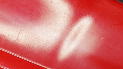
Sink Marks
Problem: One of the most commonly observed defects when it comes to injection molding is a sink mark. Sink marks are created when areas of thermal mass do not cool at the same rate. Large areas will shrink more as they cool, leading to this effect.
Solution: Adjusting the placements and parameters of features like bosses and ribscan help prevent sink marks. Good design principles include making sure that adjacent walls are of equal thickness, and to avoid any abrupt transitions from one thickness or feature size and another. Also, glossy and smooth surfaces will show sink marks better than matte and rough surfaces, so it might be possible to camouflage them in your design.
Draft Angle
Problem: Draft angles are not defects, but failure to adhere to good design principles for draft angles will create many potential defects on your parts.The purpose of a draft angle is to create a separation between the face of a part feature and the adjacent surface of the tool wall. Draft angles are calculated in the line of draw, or the direction in which the tool opens.
There is no one recommended draft angle for all applications, so it is best to consult with the process engineer if you’re unsure about the best angle for your parts.
Solutions:
Use 2° draft as a minimum clearance angle
Increase draft angles for rough surface textures
Increase draft angle to preserve uniform wall thickness
Draft angles should be incorporated with ribs, bosses and other perpendicular features
Larger draft angles help to reduce the effect of ejector pin marks
Let’s Collaborate
We hope that this list of common plastic injection molding defects and solutions helped you to identify and overcome some of your injection molding challenges. When it comes to injection molding, troubleshooting one problem may lead to another, so careful consideration of all aspects involved in the operation is necessary.
Gordon Styles is the CTO and founder of Star Rapid.