Precise lane level positioning is a critical enabler for increasing autonomy in vehicles. This capability is helping autonomous vehicles switch lanes/make turns/take corners in a secure manner depending on where they are in the lane.
More importantly, when complemented with other perception sensors, precise positioning helps cars anticipate the next maneuver and increase the safety and quality of the ride as in highway autopilot application.
Precise positioning in autonomous vehicles will also improve the performance (safety, reliability etc.) of many ADAS functions such as lane centering, lane change assistance and lane departure warning.
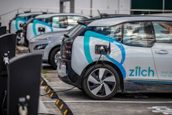
Let’s also not forget about the car sharing, ride hailing applications – they will also benefit from the improved positioning as they move from Point A to Point B including in real time parking.
The Inertial Navigation System
One of the most critical questions required for the success and safe operation of self-driving vehicles is: where am I? How does the autonomous vehicle know accurately where it is?
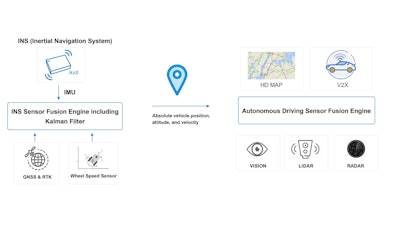
Inertial Navigation System guidance and navigation technology answers that question. The Inertial Navigation System (INS) consists of a Global Navigation Satellite System (GNSS) receiver and an Inertial Measurement Unit (IMU).
A receiver that can track not only GPS, but also one or more of the other three global navigation satellite systems (i.e., GLONASS, Galileo and BeiDou – QZSS (Japan) and IRNSS (India)) is referred as a GNSS receiver.
The role of the GNSS receiver in the Inertial Navigation System INS (let’s use the acronym as it’s already defined earlier) is to provide absolute position. Based on trilateration, GNSS positioning requires transmission from three satellites to calculate a position coordinate of latitude, longitude and height.
A fourth satellite for the GNSS receiver is used to determine the receiver clock offset compared to the atomic clock onboard the satellites and provide accurate time.
The time from the GNSS receiver can be accurate to nanoseconds and it is commonly used to synchronize sensors in the Advanced Driver Assistance Systems (ADAS), such as Inertial Measurement Unit (IMU), camera, LiDAR, etc.
The GNSS receiver provides the initial position to help with the INS initialization. Additionally, the continuous absolute position can also help to update the INS error estimates.
The IMU provides 3D rotation and 3D acceleration information from the gyroscopes and the accelerometers. The INS uses these measurements to compute relative velocity, relative position and attitude over time.
Code-based positioning techniques can result in positioning accuracies of a few meters. For autonomous driving applications that require lane level accuracy, carrier-based positioning techniques such as Real Time Kinematic (RTK) or Precise Point Positioning (PPP), are required to provide centimeter level accuracy.
For instance, when the vehicle is approaching a fork on the highway, the lane would usually become wider. Having cm level accuracy can aid the autonomous vehicles to mitigate the sharp steering motion and make it safer and smoother for the driver to exit the highway.
All about the IMU
An IMU is usually composed of two sensors – a gyroscope and an accelerometer.
The gyroscope measures angular rate of three orthogonal axes. Integrating the angular rate along the three axes over time will generate roll, pitch and yaw, which is the attitude of an object.
Similarly, the accelerometer measures linear acceleration in three orthogonal axes. Integrating acceleration over time will provide velocity and integrating velocity over time will yield distance traveled.
An IMU integrated with the gyroscope and the accelerometer can provide measurement over 6 degrees of freedom (6-DOF) (shown as below).
 An IMU uses its accelerometer and gyroscope to capture measurements over 6 degrees of freedom – three axes of movement (forward and backward, left and right and up and down) and three axes of rotation (roll, pitch and yaw).ACEINNA
Why do some IMUs include a magnetometer?
An accelerometer can also be used to calculate roll and pitch values with respect to earth’s gravitational force, and correct gyroscope drift. However, it cannot be used to detect yaw because the change of yaw is orthogonal to the gravity vector.
With regards to the earth’s magnetic field, the magnetometer measures the magnetic field strength in three dimensions. It can help to determine heading (i.e., yaw) as well as roll and pitch of the object.
Integrating a magnetometer in the IMU can help with a fast detection of the orientation of an object and also correct errors from accelerometer and gyroscope in the sensor fusion algorithm.
 ACEINNA
In ACEINNA’s inertial products, such as RTK330LA, three IMUs are used to construct a triple-redundant sensor architecture. With ACEINNA’s proprietary voting scheme, the system will only use valid IMU measurements.
Any defective sensor output or errant dataset can be ignored or de-rated in importance. This architecture ensures the reliability of the system and simultaneously improves the performance.
 Unlike vision, radar, LiDAR and other perception sensors, as well as sensors based on GNSS signals from satellites, IMU sensors are immune from harsh environmental conditions and physical obstructions like tunnels and foliage and will continue to operate.ACEINNA
INS Dead Reckoning
When the GNSS signals are compromised by traveling through a tunnel, a covered parking lot, tall city buildings or even heavy foliage, the INS can use the IMU measurements to continue to compute positions, velocities and attitude. This technique is called dead reckoning.
When the GNSS conditions are good, the GNSS receiver generates continuous positions and velocities, which are used to constrain the INS estimates. When the GNSS conditions become poor, the INS would continue to output positions, velocities and attitude based on dead reckoning for ADAS enabled navigation.
For L2+ autonomous driving, the autonomous vehicle needs to know the surroundings to be able to navigate to the destination. It needs to be equipped with perception sensors and/or HD maps to be able to know the traffic, what is ahead of the vehicle and beside the vehicle, the speed limit of the area etc.
The INS can provide precise position, velocity, acceleration, attitude and time. Unlike the perception sensors, IMU is independent of the environmental impact. If the perception sensor fails due to adverse environment, for example snow, rain or dust, the IMU can keep generating rotation and acceleration measurements for the INS to continuously operate.
To maintain ADAS features, such as lane keeping, lane centering or hands-off on highway, INS is fundamentally needed as it provides absolute positioning and redundancy in the autonomous vehicles.
The INS is also used to precisely synchronize and stabilize perception sensors in an autonomous driving system.
 For next generation autonomous vehicles, there are three critical INS requirements: high accuracy, high availability and high integrity.ACEINNA
Bias instability is one of the performance parameters of the gyroscope. It is a direct measure of the gyroscope drift over time. Because the rate output of the gyroscope is being integrated to calculate change in angles (roll, pitch and yaw), any error associated with drifts results in accumulated error in relative angles.
Furthermore, these angular errors translate into position errors over time. For automotive applications where there could be GNSS blockage situations for minutes, or longer periods of time, a high performance IMU is a necessary component in the INS for the autonomous vehicle to achieve high accuracy positioning.
For a GNSS receiver, the key to achieve high accuracy positioning is to resolve errors in distance and time from the satellites to the receiver antenna. When the satellite signal travels through the atmosphere, the ionosphere can cause delay in the signal’s transmission.
The ionospheric error is a major contributor of errors to achieving centimeter level accuracy. Due to the dispersive nature of the ionosphere, ionospheric delay varies depending on the frequency of the signal. A GNSS receiver that can track dual frequencies, e.g., L1 and L2, can compare the delays of these two signals and correct the impact of the ionospheric error.
By tracking signals from multiple constellations, a GNSS receiver can increase the availability of the receiver’s solution. When a signal is blocked due to any obstruction, the receiver can utilize a signal from another constellation to keep the solution continuously available.
If in a rare occasion, a constellation fails, the GNSS receiver can still have access to the other constellations and ensure the availability of the solution.
The measurements provided by the IMU can include several error sources. When the INS is integrating the measurement samples, the errors are also accumulating. The INS needs external reference to correct those errors and correct its position from drifting. Other than the GNSS receiver, the odometer is also an external reference.
It provides independent measurement of displacement and velocity of the vehicle to aid autonomous navigation and improves the along-track error (this is assuming the vehicle is driving on a straight course. If it’s making turn – odometer will impact both along/cross track track performance).
The integrity of a system can be described as how trustworthy the system is. The positioning accuracy of a solution is calculated in post processing when comparing the unit-under-test solution to the reference solution (i.e., the truth). In real time, the accuracy of the INS solution is unknown.
Furthermore, the trustworthiness of the solution is uncertain. An integrity monitoring system will have a protection level and an alert limit parameter. The protection level is a statistical bound error computed for each positioning solution and the alert limit is determined by the application.
The integrity monitoring system will raise an alert when the protection level is beyond the alert limit and warn the user that the INS is either unavailable or possibly generating misleading information. Integrity monitoring is critical for applications that could affect safety of life.
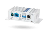
 At the 2022 CES, ACEINNA announced their ACEINNA INS40x family for autonomous vehicle navigation. It combines centimeter level precision accuracy, ease of integration and very high levels of availability, reliability and integrity, all at a very competitive price. As shown in the picture, INS401 is the 1st product in the INS40x family with one main connector and one RF connector.ACEINNA
Another factor to consider for automotive market is the cost. For L2+ autonomous driving, with perception sensors and HD maps equipped, it would require cloud infrastructure and maintenance and a lot more processing power in real time, which would add significant cost to the autonomous driving system.
Correction providers would also need to charge a fee for service subscriptions to maintain their infrastructure and expand their coverage. Fortunately, technologies for MEMS INS are developing at a fast pace and it allows the cost for INS to be suitable for scalable applications.
The Inertial Navigation System is essential to autonomous vehicles. It provides timing information for sensor synchronization and required input for the ADAS (Advanced Driver Assistance Systems) system, such as velocity, position, attitude at high sampling frequency.
It complements perception sensors for localization. To achieve highly accurate localization with high availability, it is critical to utilize an INS that has dual-frequency GNSS receiver and high performance IMU with the RTK capability.
Implementation of integrity monitoring in the INS is also crucial for automotive applications as it falls under safety-critical applications. In extreme cases, when the environmental adversity causes the perception sensor and the GNSS receiver to both fail (intermittently or permanently), ADAS can continue to work based on dead reckoning due to the self-contained nature of the IMU until the vehicle pulls over safely.
---
Claire Liu is Product Marketing Manager at ACEINNA Inc., currently responsible for the RTK/INS product line. She has a BSc and MSc in Electrical Engineering from Southeast University and University of Calgary, respectively. Ms. Liu joined ACEINNA in April 2021 from NovAtel, where she was a Technical Marketing Engineer overseeing competitive evaluation and product differentiation.
ACEINNA, headquartered in Tewksbury, Massachusetts, is a leading provider of innovative silicon and MEMS sensor, and solutions, committed to solving the world’s most challenging and complex sensor and sensing problems. ACEINNA is a fast growing, pure-play sensor company at the forefront of sensor innovation with a demonstrated track record of designing, manufacturing, testing and marketing high performance and cost-effective MEMS based inertial sensors and magnetic current sensors and ASICs for automotive, and industrial markets enabling electrification and autonomous driving. The company has manufacturing facilities in Wuxi, China, and R&D facilities in San Jose CA, Andover MA, and Chicago IL.